So... Introducing my 'Calimero' BEAM robot.
BEAM robotics is the brain child of Mark W. Tilden. BEAM stands for a triple acronym:
| Biology | Electronics | Aesthetics | Mechanics |
| Building | Evolution | Anarchy | Modularity |
| Biotechnology | Ethnology | Analogy | Morphology |
But in short, these BEAM robots usually refer to small autonomous robots, often solar-powered, and with a minimal or no 'central nervous system' (read: no complex computer'brains',) strongly resembling insects in their behaviour or appearance.
I like BEAM bots, they're very, very inexpensive to build, most simple examples you can build out of scrapped hardware, they're unbelievably simple in design, yet exhibit complex behaviour, what more does one want?
The little robot I hereby document is called Calimero, because it eventually will sport a styrofoam and papier-maché representation of this cartoon figure. Why, you ask?
I could tell you, there's a good reason for it, but it's rather personal, and blogs are already boringly personal enough, heehee! :p
My 'bot of the day is based -or rather: bit by bit slavishly copied from - on Wilf Rigter's version of the 555 photopopper circuit.
In short, it contains two small motors, fed by a solar-cell, and it has two 'eyes' made out of photodiodes. The solar-cell charges a capacitor, which when full, releases its energy to 'fire' the circuit, which drives the engine(s).
So this little statuette of Calimero just sits there, and now and then, depending on how much ambient light there is, it twitches a bit, each twitch a little nudge forward. Because there are two motors and two 'eyes,' it orients itself towards the brighter lightsource, following it, to get even more energy.
So it errr... Follows bright light, gottit?
Now this simple robot could be built very small, but since it will eventually have a little statuette atop of it, measuring approx 10-15 cm., building it as compact as possible is not a priority, so I thought about building it inside a plastic screw-top lid of a big jar.
The reason: it provides a reasonably sturdy yet light-weight chassis, ample room, and the circular outer rim is good to prevent it from getting stuck into corners too easily.
Assembly:
 1.) Motors.
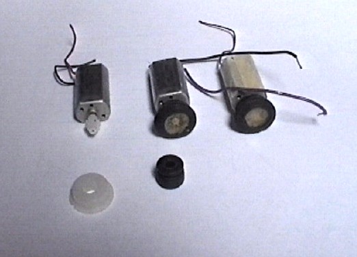
Let's start with the very stuff that makes the robot move: bog-standard electromotors.
These are motors from CD tray mechanisms; the black rubber sleeves comes from said same mechanism's vibration-mounts, those are incredibly flexible, and with a bit of effort they neatly slide over the wheels, which come from cassette-deck mechanisms.
I added some contact glue to the mix to make sure the contraption sticks. (Lame pun intended.)
Then I applied some paper tape partway around the housing of the motors, so I don't run the risk of short-circuiting when placing them next to each other.
(And yes: I didn't find my plastic insulator tape, you guessed that right.)
Oh, and to be tidy, I desoldered the original wires and resoldered my own, colour coded ones. The motors were the same but came from different mechanisms, so the wires had four different colours, tsk ;)
 2.) Carriage.
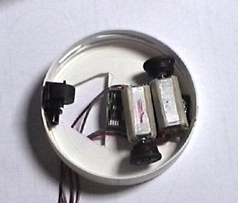
This screw-top measures about 8 cm. in diameter, to give you an idea of dimensions...
The two motors and wheels are glued inside it, atop of a piece of scrap PCB, to adjust height. I cut a hole into the top of the lid to allow for wires to poke through, so I didn't have to fiddle too much getting stuff where I wanted it. The trailing wheel is a cassette-deck pinch-roller wheel, made out of rubber. You undoubtedly notice the wheels/motors assembly is fitted in a weird way, that was to make sure it will never run in a straight line, because I didn't want that to happen. I prefer a slightly wobbly way of movement, it increases the chance for the 'eyes' to notice a brighter spot because in this way the robot constantly 'looks' a little bit left and right when moving around and anyways, the screw-lid is too small to allow for a placement that allows a perfect straight way of movement, without letting the wheels stick out beyond the circular edge. I also didn't want that to happen, otherwise it would nullify the do-not-get-stuck advantages of a circular enclosure... (Duh.)
 3.) Energy-storage.
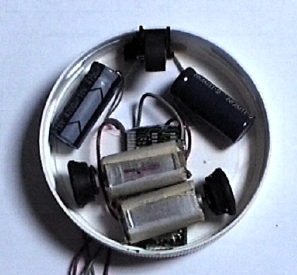
Hmmm... I then noticed I had spare room left inside the enclosure so I added two capacitors.
This little robot I didn't take much time to think about in advance, it was so simple to make it possible to take the build-as-you-go approach, so this was a nice bonus. Before I noticed I had ample room to spare, I thought I would assemble the capacitors on the other side, now that's not neccesary, and has the added benefit the centre-of gravity of this thing is nice and low, the motors and capacitors providing the bulk of mass, nice, nice...
The capacitors, you could compare them to accu's; they store the energy from the solar-cell, and when full, they discharge their stored energy in one go into the motors. If you would just connect the solar-cell to the motors, those would never run, because the power from the cells isn't enough. So that power gets 'saved' into the caps, until there's enough of it to make te motors spin for a short while.
These capacitors aren't extremely big: 4700uF, a nice size in-between: smaller ones make the engines fire more often, but the movements then become really twitchy, now they roll a little ways instead of really 'nudging...' I didn't experiment with really small values, but probably will in another robot, giving a near-continuous movement-effect, though probably very jerky, I think it will give a creepy impression of an insect on caffeine, grin. (Yeah, insect on wheels??? That'll look convincing!)
 4.) Igor, bring me a brain!
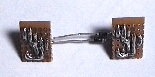
I said these 555-photopoppers contraptions were small, and my statuette was to be reasonably big, so I didn't go for the super-miniature way, but chose to put the ciruits on veroboard. This picture shows the backside, so you can all mock my l33t soldering skills.
In reality it looks much better, remember, this is a shot made with a handheld Hi8 analog camera, and it looks out of focus, which is in fact the digitising going a bit haywire...
Actual size approx 1.5 x 2.25 cm. And you can clearly see I could've easily made it smaller than that. I could've cut off the left side and the top side, but I didn't need really to, so of course I didn't. (Laaaaazzzzzzzyyyyyyyy!)
 5.) Igor, bring me another brain!
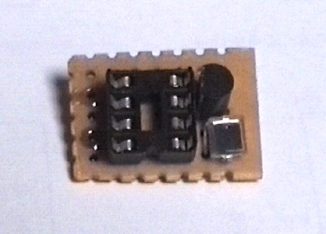
This is actually the same one, component side, but they are identical, so just to give Igor some work, I pretend it is the other one. Ahem, errr... Right.
Left the 8-pin DIL socket, currently without the CMOS-555. At the right side, on top a simple transistor, and beneath that a photodiode. That's all it takes. All one has to add is some wires to connect it to the solar-cell, the capacitors, and of course the motors. Oh, and two diodes, so they can -partially- share the power, stored in the capacitors.
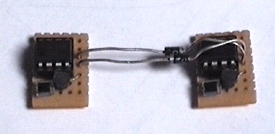 6.) Sometimes the twain do meet.
I told you they were hard to distinguish from eachother :) Two identical circuits, connected with a set of diodes, so that when one solarengine gets a power 'shot', the other one gets one too, but with a small bias, the diodes make sure the second engine gets slightly less power, so the engines run with a speed-difference, which makes the robot turn.
Now in hindsight, I should've thought about a way to build these things so the 'eyes' were placed more mirror-symmetrically, but of course, at the moment of soldering, I didn't think about this, darn-diddely-dandy! Putting the photodiodes on 'stalks' would be a nice idea for another built into the future, so one can aim the way they 'look'. It would also make the possibilities to built it inside an arbitrary enclosure much simpler. Hmmm... The veroboard idea seems less optimal by the minute.... Designs this simple really don't need to be soldered onto PCBs or veroboard, heh.
 7.) It's alive!
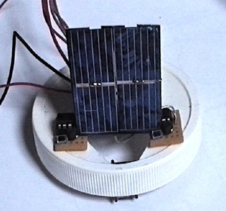
So, everything in place, now it's time to assemble the pieces, and add a solar cell...
And it works! Igor it lives! Igoooooor!!!
Ahem. Errr... (Pants.) The trailing wires are testleads, and temporary connections to see whether it really works before soldering the bunch together. These are pictures of Rev. 1.1, which didn't perform very well....
For starters, now both the eyes are pointed upwards, which in itself isn't too bad, because 99% of lightsources come from above, like the sun and a bureau-light, but they capture equal amounts of light in most of the cases which didn't help the critter's phototropic behaviour... So I flipped the assembly 90° and bent the connecting diode-leads so that now the eyes look forward and more sideways, a bit like, say a dog...
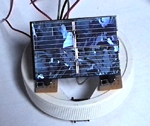 Then the solar-cell, sigh... This second picture has the cell assembled differently, in a 45° angle, because I thought it didn't catch enough light, but these cells just... Don't deliver. These cells are cheap, and you can buy them in most electronics' shops, they come in a plastic shell with a transparent top, which contains lenses to increase its efficiency, but, alas, it doesn't help much. I went back to several shops, asking for something better, but the better cells aren't popular enough to stock, so it seems. One man told me these ones are in fact only good for demonstration purposes, not for actual use, argh!
So what to do? Sure the robot functioned, but it was terribly 'lazy,' only doing its thing when the light was very bright and even then it only triggered in big intervals...
The answer is simple: you remember the solar-powered calculators, popular in the 80's and 90's? Those tiny cells are actually much better than this variety, and you can find them for pennies in boot-car sales, attics, eBay etc. So if you spot one, make sure to lay your grubby hands on it.
Now it works better, and has a solar cell that is much smaller to boot.
Picture, you say? Ah, yes.... Maybe one day. (Laaaaaaaaazzzzzzzzzyyyyyy!!!!!!)

No comments:
Post a Comment